| From | 1 | 2 | 4 | 3 | 6 | 1 | 2 | 8 | 10 |
| To | 3 | 4 | 12 | 5 | 11 | 14 | 7 | 9 | 13 |
220V,
DC Supply

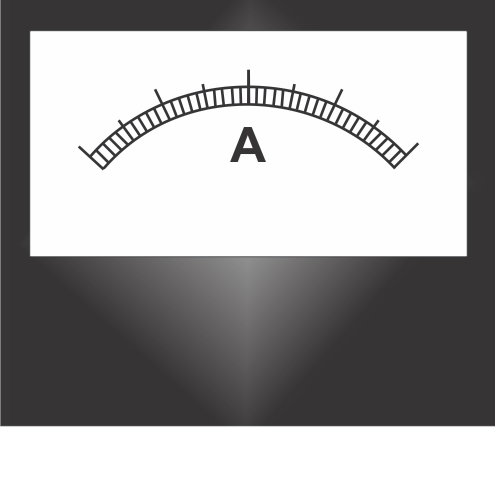
Ammeter
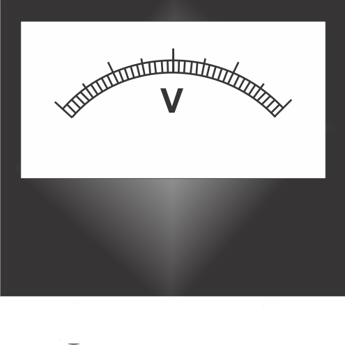
Voltmeter
Ammeter
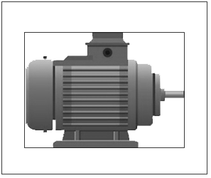
DC Shunt Motor
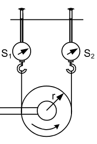
Move the slider ➤


Rotor View
| Speed |
|---|
| SN | Armature Current | Field Current | Speed | S1 | S2 | Torque |
|---|
Armature Current vs Speed Graph
Instructions
Step 1: Make the proper connection by clicking the node as instructed below. If the wire is misplaced, click the node number to deattach the nodes' wire.
Step 2: Click "Check" button.
if connection is correct, an alert appers. Click ok. Now, go to step 4.
if connection is wrong, an alert appers. Click ok. Now, go to step 3.
Step 3: Check the connection, if incorrect, click on node number to remove any
particular
connection(s) or click on reset button and start from step 1.
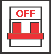
Step 4: Switch on the MCB.
Step 5: Move the slider to change the load values
Step 7: Take readings from Rotor, Voltmeter, Ammeter, Watt-meter and load values.
Step 8: Click "Add to table 1" button to insert the values in the table 1.
Step 9: Click "Add to table 2" button to insert the values in the table 2.
Step 10: Follow the procedure from step 6 to step 8, till you have the >=6 readings on the table.
Step 11: After taking minimum 6 readings, click the "Graph" buttons(1, 2, and 3).
Step 11: Click "Print" button, to print the full connections with graph and table in landscape mode.
Step 1: Make the proper connection by clicking the node as instructed below. If the wire is misplaced, click the node number to deattach the nodes' wire.
| From | 1 | 2 | 4 | 3 | 6 | 1 | 2 | 8 | 10 |
| To | 3 | 4 | 12 | 5 | 11 | 14 | 7 | 9 | 13 |
Step 4: Switch on the MCB.
Step 5: Move the slider to change the load values
Step 7: Take readings from Rotor, Voltmeter, Ammeter, Watt-meter and load values.
Step 8: Click "Add to table 1" button to insert the values in the table 1.
Step 9: Click "Add to table 2" button to insert the values in the table 2.
Step 10: Follow the procedure from step 6 to step 8, till you have the >=6 readings on the table.
Step 11: After taking minimum 6 readings, click the "Graph" buttons(1, 2, and 3).
Step 11: Click "Print" button, to print the full connections with graph and table in landscape mode.