For Open Circuit Test
| From | 1 | 2 | 3 | 7 | 8 | 7 | 8 | 9 | 10 | 13 | 14 | 15 | 16 | 17 | 18 | 19 | 24 | 32 | 33 |
| To | 4 | 5 | 6 | 9 | 10 | 32 | 33 | 11 | 12 | 30 | 31 | 21 | 20 | 26 | 25 | 27 | 28 | 29 |
MCB


R
E
C
T
I
F
I
E
R
Voltage Regulator
Move the slider
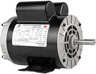
DC Motor
3 Phase Alternator
| O.C. Test Motor Speed |
|---|
| S.C. Test Motor Speed |
|---|
Field Regulator
( DC Motor )
Move the slider ➤
Field Regulator
( Alternator )
Move the slider ➤
Ammeter
Ammeter
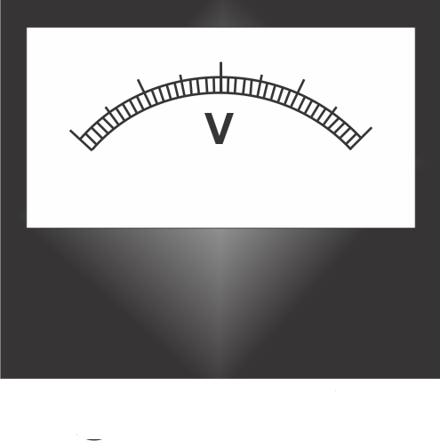
Voltmeter
| SL. NO. | SPEED | FIELD CURRENT (A) | ALTERNATOR INDUCED EMF (V) |
|---|
| SL. NO. | SPEED | FIELD CURRENT (A) | ARMATURE CURRENT (A) |
|---|
Induced EMF VS. Field Current Graph
Armature Current VS. Field Current Graph
Instructions
Step 1: Make the proper connection by clicking the node as instructed below. If the wire is misplaced, click the node number to deattach the nodes' wire.
For Open Circuit Test
For Short Circuit Test
Step 2: Click "Check" button.if connection is correct, an alert appers. Click ok. Now, go to step 4.
if connection is wrong, an alert appers. Click ok. Now, go to step 3.
Step 3: Check the connection, if incorrect, click on node number to remove any particular
connection(s) or click on reset button and start from step 1.
Step 4: Switch on the MCB.
Step 5: Follow instruction manual and also follow alerts
Step 1: Make the proper connection by clicking the node as instructed below. If the wire is misplaced, click the node number to deattach the nodes' wire.
For Open Circuit Test
| From | 1 | 2 | 3 | 7 | 8 | 7 | 8 | 9 | 10 | 13 | 14 | 15 | 16 | - | 18 | 19 | 24 | 32 | 33 |
| To | 4 | 5 | 6 | 9 | 10 | 32 | 33 | 11 | 12 | 30 | 31 | 21 | 20 | - | 26 | 25 | 27 | 28 | 29 |
For Short Circuit Test
| From | 1 | 2 | 3 | 7 | 8 | 7 | 8 | 9 | 10 | 13 | 14 | 15 | 16 | 17 | 18 | 19 | 24 | 32 | 33 |
| To | 4 | 5 | 6 | 9 | 10 | 32 | 33 | 11 | 12 | 30 | 31 | 23 | 22 | 16 | 26 | 25 | 27 | 28 | 29 |
Step 2: Click "Check" button.
Step 4: Switch on the MCB.
Step 5: Follow instruction manual and also follow alerts